Networking Basics: How to Configure and Verify EIGRP with IPv6-idL

Today, we're going to focus on the three-component process for configuring, applying, and verifying Enhanced Interior Gateway Routing Protocol (EIGRP) as the routing protocol to a Cisco network. For basics on EIGRP, check out Anthony Sequeira's What is EIGRP for IPv6? MicroNugget.
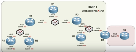
Below is a visual representation of the network topology used in this example.

The network is represented by the string 2001:db8:6783:X::/64, located in the upper right corner of the diagram. X is not a hexadecimal character, however, and in this case indicates the subnets represented elsewhere in the graphic.
In this example case, R2, R4, R5, R6, half of R7, and R3 have been EIGRP preconfigured. The focus, then, is on enabling EIGRP on R1.
Configuring EIGRP Router ID
In IPv4, EIGRP router ID configuration was not a necessary step, but in IPv6 it becomes necessary. To begin, bring up router configuration mode for R1. Enter the command ipv6 router eigrp 1, followed by eigrp router-id 1.1.1.1.
The 1.1.1.1, while it may look like an IPv4 address, is simply a representation of EIGRP on R1. It is important to avoid duplicating router IDs across devices, as each must be unique in order to function properly.
Enabling the Router Process
In IPv6, the routing process is shut down by default, and requires a specific command to bring it back up. While still in config-rtr, enter no shutdown followed by exit to disable default shutdown.
Entering Interfaces
The third step in the process is manually putting interfaces into EIGRP. Unlike IPv4, IPv6 does not utilize network statements to include interfaces. Instead, it requires use of interface configuration mode.
Similarly, the network statements for things like RIP and OSPF are also now implemented in interface configuration mode rather than router configuration mode.
First Interface
After exiting router configuration mode as indicated by the previously-mentioned exit command, the next step is to enter interface configuration. Enter int g1/0 to bring up configuration for that interface.
Next, enter ipv6 eigrp 1. This command invites G1/0 to participate in IPv6 EIGRP autonomous system 1. Finally, enter end to exit interface configuration mode.
Adjacencies
Immediately, R1 will return with adjacencies from R2 (FE80::2) and R3 (FE80::3). Using the link local addresses, R1 has exchanged the route update as indicated in the screenshot below.

Verifying the Results
To verify the configuration, the broad first step would be to show the IPv6 routing table. If it shows up in the table, its implementation is verified. In case of issues, however, there are intermediate verification steps as well.
Participating Interfaces
Another method is to query the router for any interfaces participating inside of EIGRP. To do so, enter show ipv6 eigrp interfaces. This will return a list of participating interfaces, which in the case of R1 is only G1/0.
Verifying Neighbors
The next step in verification is displaying R1's neighbors. Here, commands are very similar to IPv4. Enter show ipv6 eigrp neighbors. The table should display the link local addresses for R2 (FE80::2) and R3 (FE80::3).
Updates occur every five seconds, and in this case the hold down timer is set to 15 seconds. This indicates that, if a neighbor is unresponsive for 15 seconds, R1 will assume that it had a problem and will disassociate any routes learned from that neighbor.
Checking Other Routers with Ping
If everything is working properly, every router should have a full route to everything. To verify this, bring up the R4 portal and show the routing table with show ipv6 route eigrp. In this example, the last entry, denoted by EX as an external route thanks to RIP next generation redistribution, is represented by the address 2001:DB8:6783::8888::/64. This is the address of R8 in the graphic.
To verify the path between R4, enter ping 2001:DB8:6783::8888::8. That last 8 in the string indicates the loopback interface on R8. If all is correct, it will return a success rate of 100%.
Verifying Path
The last verification step is to trace the path between R4 and R8. To do so, enter trace 2001:DB8:6783::8888::8. This command will display the individual "hops" between the two routers, which is predicted to be R4 to R2 to R3 to R7 to R8, for a total of four hops.
After running the trace command, it should return the predicted path, indicated by the last number in each of the address strings (2, 3, 7, and 8).
The three basic steps for EIGRP configuration are to set the router ID, disable the no shutdown default, and then invite the interfaces to participate in the EIGRP autonomous system. After doing so, and depending on the results, this MicroNugget has also covered the various means of verification.
CBT Nuggets IPv6 Training
Trainer Keith Barker has created the following IPv6-specific training.
Keith also shares more on this topic right here:
delivered to your inbox.
By submitting this form you agree to receive marketing emails from CBT Nuggets and that you have read, understood and are able to consent to our privacy policy.